
What is a safety light curtain?
PRODUCTS
-
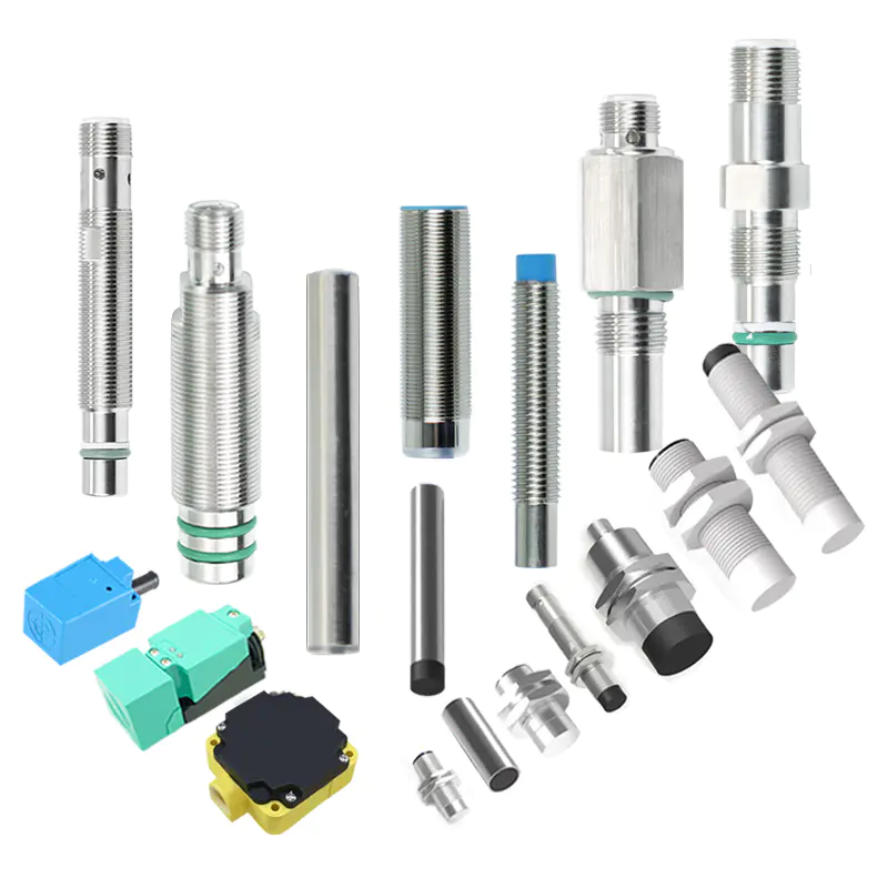
Inductive proximity sensor
- Square Proximity Sensor
- High temperature proximity sensor
- Low temperature proximity sensor
- ring proximity sensor
- Standard inductive proximity sensor
- Ultra Small inductive proximity sensor
- Long Distance Proximity Sensor
- Corrosion resistant proximity sensor
- metal face proximity sensor
- high pressure proximity sensor
- Analog proximity sensor
- namur proximity sensor
-
Laser sensor
- Explosion-proof laser distance measurement sensor
- Laser distance measurement module
- Intelligent driving system
- Laser hot and cold metal sensor
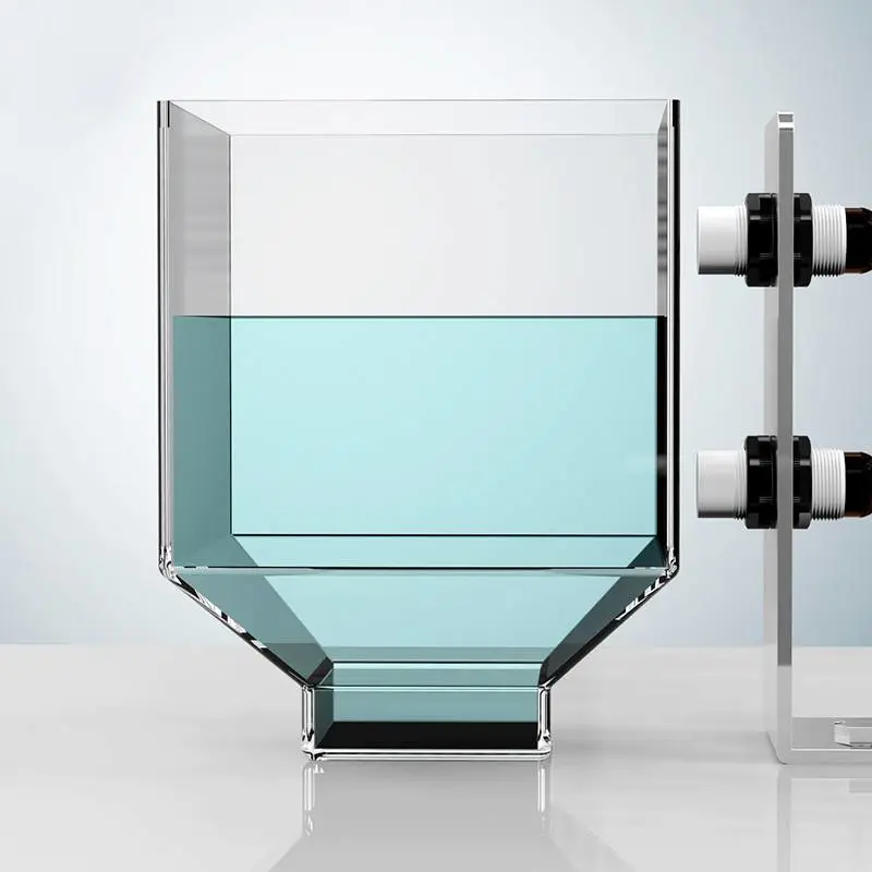
- Laser liquid level sensor
- TOF laser photoelectric sensor
- High-precision displacement sensor
- Amplifier built-in TOF laser sensor
- High frequency laser distance sensor
- High-precision laser distance sensor
- Capacitive proximity sensor
-
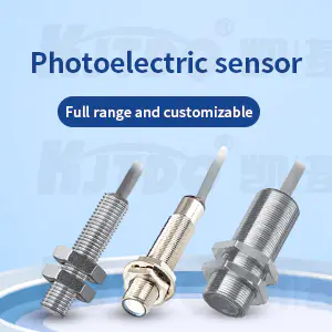
Photoelectric sensor
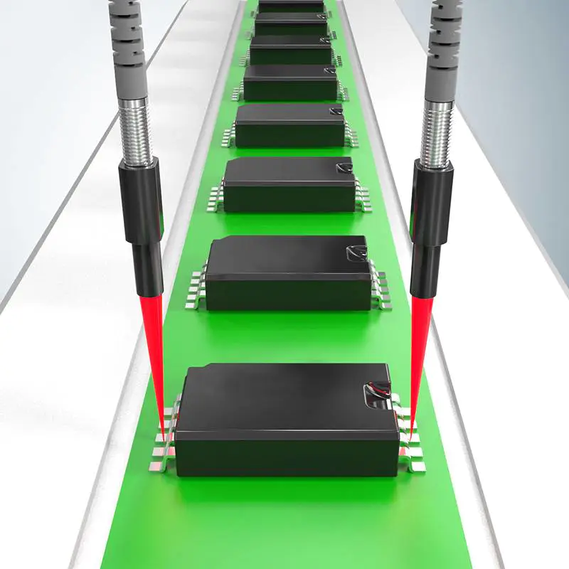
- Traffic collision protection device
- Square series
- Optical fiber
- Fiber amplifier
- standard series
- Cylindrical Photoelectric sensor
- Slot type Photoelectric sensor
- Square type Photoelectric sensor
- Long range Photoelectric sensor
- Optical fiber sensor
- High temperature Photoelectric sensor
- Laser Photoelectric sensor
- Color mark sensor
- Small photoelectric sensor
- Safety light curtain
- Megnetic Sensor
- Speed Sensor
- Textile special sensor
- Limit switch
- Vibration Sensor
- Measuring sensor
- Wireless sensor
- Conveyor belt protection devices
- Sensor accessories
how to create a garage door proximity sensor
by:KJTDQ
2020-05-16
If you don\'t have a reverse backup radar system in your car, or if you park forward in the garage, would you probably know the feeling of \"Am I too close\" and would I hit the wall? ? \".
There are many ways to solve this problem, but if you like to patch electronics and write code, there is only one way: create a homemade electronic system.
I used a single chip microcomputer and a HC-
SR04 ultrasonic sensor, but of course you can easily replicate this proximity sensor with any micro controller you like.
We will first learn how to measure the distance with an ultrasonic sensor and test the measurement using a 2*16 LCD display.
After we put this part down, we will use 4 LEDs instead of an LCD display to implement an intuitive way to show the distance from the wall.
I won\'t go into details on the basic features of the PIC micro-controller, but you can find more information on how to set up the tutorial for the PIC micro-controller programming tool and how to write your first PIC program.
Here is a list of the components we need: Let\'s build the circuit on the breadboard.
First connect the power supply to the power rail on the bread board.
Do not power the entire circuit until it is finished.
The ultrasonic sensor has 4 pins: Vcc, Trig, Echo, and Gnd.
In order to use it, we will generate a high pulse on the trigger pin, then the Echo pin will produce a high signal and the duration will tell us how long it will take for the sound to go from the module to the obstacle and back.
Connect the Vcc to the 5v track and the Gnd to the ground.
Pin RA6 to connect Trig to PIC (pin 15)
And Echo to RA7 (pin 16).
If a different micro-controller is used, Trig should connect to any digital output and respond to any digital input.
For the LCD display, we will make the following connection, which you can also see on the attached schematic: we need to do a little math to figure out how to get the distance when the sensor gives us a duration.
As a reminder, HC-
The SR04 will output a high signal on its Echo pin, the duration of which will be the time it takes for the signal to propagate from the Trig pin to the object and return.
So we need to divide this time by 2.
We will see how to calculate the time using the following micro-controller.
Let\'s say we have this time in seconds.
The speed of sound is v = 340.
3 m/s, that is, v = 34030 cm/s.
The speed is calculated by v = d/t, with d as the distance and t as the time.
Therefore, the distance is equal to d = v * t, that is, d = (34030*t)/2.
This gives us d = 17015 * t.
The first thing we need to do is get the duration of the Echo pin to generate a high signal.
We will use Timer1 on photos.
Let\'s configure it using the t1 con register.
First, set the clock source to an internal clock.
This means that the clock frequency used by the timer will be Fosc/4 and 2 MHz in our case because our clock is set to 8 MHz.
When we use the internal clock as the source, we can disable the timer1 oscillator.
Initially turn off the timer and set the voltage divider to 2:1.
This means that the frequency of the timer will be half of the clock source, that is, 1 MHz.
That is to say, the timer value will increase every 1us.
This gives us time _ s = timer_time/1000000.
Therefore, d = 17015 * time_time/1000000, that is, d = 0.
017015 * time_time, or d = timer_time/58. 77.
The code used to configure the timer is the following code for the C language of the x8-compiler.
Let\'s specify the code to HC-
Divide SR04 into separate metric values. c and . h files.
Here is the contents of the header file: Here is where we just need to change these definitions, not change the values anywhere in the code that is used.
Even if you don\'t need the system to tell you how close your car is, we will write one that will keep updating the meter.
There are many ways to improve efficiency.
One of the best ways is to use the PIR sensor to detect motion.
When motion is detected, it triggers an interrupt on the PIC and starts the entire measurement/update meter process.
To keep it simple and to use only the components we have already used, we will simply put the system into sleep after each reading.
But when the car is not in the garage, when the car stops but no longer moves, we need to put the system in idle mode.
To do this, we will use two different durations for loop latency, and we will add a counter of the same distance: Here is the logic we will use: in the first two cases, we want the led off.
All we need to do is call update _ proxim _ meter ()
The distance is greater than the maximum threshold.
Here is the code for the main loop: As you can see, the code for the main loop greatly improves the readability and manageability of the program.
In this example, even without knowing the internal work of each function, anyone can quickly understand the role of the program.
If you have done a little experiment with the distance meter, it is easier if you still connect the LCD display, you may notice that the distance value of a reading sometimes jumps, even if the object is barely moving.
There is an easy way to solve this problem and make the system more reliable.
We will filter these values by simply averaging the metric values of a given number.
Let\'s revise our metrics. c and . h files.
Function HCInit ()
Now, I will make an argument about the number of measures.
We will limit it to 5 samples per measurement, so it doesn\'t take much time to get the distance.
We will use a static variable _ samples, which is accessible by all functions in that file but not by any other file.
Here is the modification code of HCInit ()
Function: now we only need to cycle the _ sample time HCCalculateDistance ()
, And calculate the mean value of the n _ samples value: In this way, now the distance returned by hccalculdistance ()
It will be smoother and this should eliminate the wrong value.
The full code for this project can be found on my Github page.
As promised, let\'s compare the memory consumption of this program to the memory consumption when we have an LCD display.
It\'s much smaller than before, just because we removed the code related to the LCD display.
The size of the program memory is half that of the previous one.
We also added some code for mean and delay logic!
The results when moving the system closer/farther away from the wall are shown in the attached video.
There are many ways we can improve this device.
I \'ve listed some below, but feel free to try and implement your own ideas!
Thank you for reading and I hope it helps!
Don\'t forget to check out the embedded lab for more tutorials!
Custom message
Related Products


![[Good news] Nanjing Institute of Technology joins hands with Kaijit to establish an “off-campus practical education base”](https://img80002753.weyesimg.com/uploads/www.kjt-sensor.com/images/17133382885300.jpg?imageView2/2/w/1920/q/75/format/webp)


![[Good news] KJT was awarded the](https://img80002753.weyesimg.com/uploads/www.kjt-sensor.com/images/17132350274153.jpg?imageView2/2/w/1920/q/75/format/webp)
![[Invitation Letter] 2021SIA Dongguan Smart Factory Exhibition and DME Dongguan International Machine Tool Exhibition](https://img80002753.weyesimg.com/uploads/www.kjt-sensor.com/images/17132347116490.jpg?imageView2/2/w/1920/q/75/format/webp)
![[Good news] Kaijit passed the national high-tech enterprise review and certification](https://img80002753.weyesimg.com/uploads/www.kjt-sensor.com/images/17132343883285.jpg?imageView2/2/w/1920/q/75/format/webp)