
What is a safety light curtain?
PRODUCTS
-
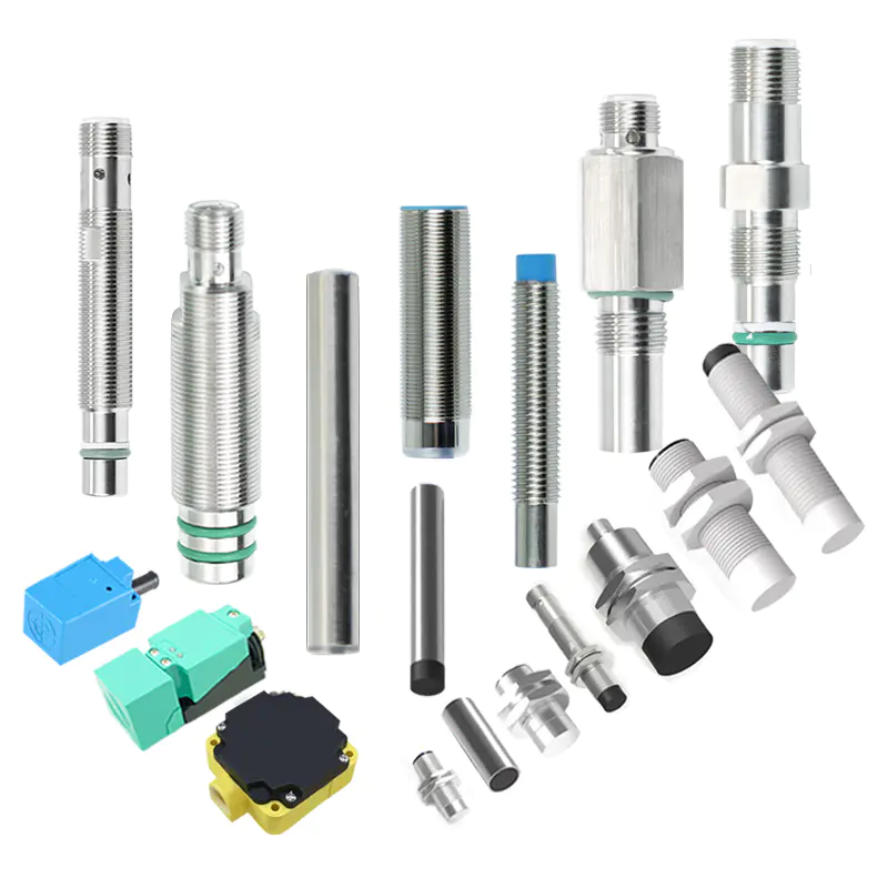
Inductive proximity sensor
- Square Proximity Sensor
- High temperature proximity sensor
- Low temperature proximity sensor
- ring proximity sensor
- Standard inductive proximity sensor
- Ultra Small inductive proximity sensor
- Long Distance Proximity Sensor
- Corrosion resistant proximity sensor
- metal face proximity sensor
- high pressure proximity sensor
- Analog proximity sensor
- namur proximity sensor
-
Laser sensor
- Explosion-proof laser distance measurement sensor
- Laser distance measurement module
- Intelligent driving system
- Laser hot and cold metal sensor
- Laser liquid level sensor
- TOF laser photoelectric sensor
- High-precision displacement sensor
- Amplifier built-in TOF laser sensor
- High frequency laser distance sensor
- High-precision laser distance sensor
- Capacitive proximity sensor
-
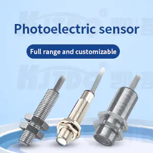
Photoelectric sensor
- Traffic collision protection device
- Square series
- Optical fiber
- Fiber amplifier
- standard series
- Cylindrical Photoelectric sensor
- Slot type Photoelectric sensor
- Square type Photoelectric sensor
- Long range Photoelectric sensor
- Optical fiber sensor
- High temperature Photoelectric sensor
- Laser Photoelectric sensor
- Color mark sensor
- Small photoelectric sensor
- Safety light curtain
- Megnetic Sensor
- Speed Sensor
- Textile special sensor
- Limit switch
- Vibration Sensor
- Measuring sensor
- Wireless sensor
- Conveyor belt protection devices
- Sensor accessories
long range ultrasonic distance sensor -
by:KJTDQ
2020-04-19
This note demonstrates a way to increase the measurement range of popular HC-
Ultrasonic distance sensor SR04.
The enhancement within the scope is based on reducing the \"Field of View \"(FOV)
Part of the basic sensor, which is used as a feed element for a parabolic disc.
No changes have taken place in the electronic equipment of the basic HCSR04 sensor.
However, a blanking circuit is added externally in order to ignore the first reflection/distance from the feed element to the parabolic disk. The HC-
The SR04 is connected to the Arduino uno, which displays the measured distance on the standard PC1602 16x2 LCD display.
The distance is also sent on the serial link via the USB connector.
For outdoor experiments, the system uses a mobile power supply group to power through a USB connector.
Maximum distance 9.
Compared to the 24 m specified by the basic sensor, 4 m was achieved in the experiment.
I would like to thank emir for his useful input in the project blog, who provided a great tear in the blogdown of the HC-
SR04 ultrasonic distance sensor: Specification of HC-
The SR04 ultrasonic sensor indicates a measuring angle of 15 °.
When used as a feed element for dish dishes, in order for the dish to shine completely, it needs to be placed in a position far enough from the dish.
In order for the focal length to meet this requirement, a shallow disk is required.
Select the old frying pan with a diameter of 250mm and a depth of 16mm as the parabolic tray.
The standard calculation of sound in 40 kHz Air indicates a focal length of 24.
4 cm and FOV/beam width 2. 31 deg.
The measurement angle/field of view is reduced from 15 ~ 2 degrees.
3 ° will be used to provide an increased measurement range. The pan handle-
Modify the arrangement and paste the appropriately curved aluminum tube on the handle holder to form a feed support beam. The HC-
The SR04 sensor is fixed at the center line of the parabolic disc at a distance of about 24 cm. The HC-
The SR04 sensor outputs a Forward echo pulse when triggered by a narrow forward trigger pulse.
In normal operation, the width of the echo pulse is proportional to the time required for the 40 kHz pulse sequenceand-
The distance from the object being reflected.
In the air of 330 met/sec, the nominal speed of sound a 1 mile-
The second pulse width corresponds to the range of 16. 5 cm and a two-
33 cm way to travel.
Therefore, when the feed distance is about 24 cm, the distance will correspond to 1. 45 milli-
Sec or 1450 micro-sec.
Without providing a blanking circuit that ignores this shorter distance, it is impossible to determine the longer distance from the parabolic disk to the reflecting object.
The blanking circuit shown is a simple singlestable multi-
Use three vibrator circuits built. Schmidt-inverter gates.
The output of the blanking circuit will lower the detection threshold, which is related to ~ The high signal requirements of 2 correspond. 5 milli-
Seconds, so ignore the distance of about 40 cm.
This value should be greater than 24mm, but less than 48 cm, so that the minimum distance from the front of the feed point can be measured.
If there is no blanking circuit, the distance is 23 cm.
After studying Hc-
The SR04 observed that the threshold signal from the OTP controller pin 9 reached pin 2 of The LM324 U2A through a 75 k ohm resistor.
However, when we compare it to the actual HC-
SR04 hardware we see the LM324 marked as U1.
According to the circuit diagram, the blanking output of the additional blanking circuit is connected to pin 2 of U2A and pin 2 of U1.
There are usually 4 connected to HC-
SR04: Vcc, Trig, Echo and Gnd.
Now add an additional wire marked as blank as the fifth connection.
A mosaic of bread-
The circuit board and schematic diagram of the whole system are standard with the connection of ultrasonic sensors and LCD, and have detailed documentation.
The prototype circuit is connected to a perforated circuit board that constitutes a shield for the Arduino uno.
The LCD is connected to the top of the board.
For outdoor experiments, the system uses a mobile power supply group to power through a USB connector.
Attached is the Fritzing project file with Arduino code.
Custom message
Related Products


![[Good news] Nanjing Institute of Technology joins hands with Kaijit to establish an “off-campus practical education base”](https://img80002753.weyesimg.com/uploads/www.kjt-sensor.com/images/17133382885300.jpg?imageView2/2/w/1920/q/75/format/webp)


![[Good news] KJT was awarded the](https://img80002753.weyesimg.com/uploads/www.kjt-sensor.com/images/17132350274153.jpg?imageView2/2/w/1920/q/75/format/webp)
![[Invitation Letter] 2021SIA Dongguan Smart Factory Exhibition and DME Dongguan International Machine Tool Exhibition](https://img80002753.weyesimg.com/uploads/www.kjt-sensor.com/images/17132347116490.jpg?imageView2/2/w/1920/q/75/format/webp)
![[Good news] Kaijit passed the national high-tech enterprise review and certification](https://img80002753.weyesimg.com/uploads/www.kjt-sensor.com/images/17132343883285.jpg?imageView2/2/w/1920/q/75/format/webp)